Wednesday, February 16, 2022

Building the MEGA65 core for NEXYS4-DDR ( A7 )

The question here is, why build your own core?  Well there really isn't any reason for the average user to do this.  However if you're interested in dabbling with the code and trying to see how it works, building your own core is really the only way to learn.

If you don't want to build your own core, just get the official core from here:

https://files.mega65.org/html/main.php

So without further-a-do here it is, I hope you find it interesting even if it's not useful to you.

Development Board : NEXYS4-DDR


The NEXYS4-DDR development board uses the XC7A100T-1CSG324C fpga
 
It should be noted that this board has been replaced by the NEXYS A7.  
The website suggests this board is nearly identical. 
There are TWO versions of the A7 a 100T and a cheaper 50T.
You will need to more expensive100T version. 

Virtual Machine : VMware Workstation

 
For this exercise I will building my Dev box using VMware Workstation, simply because I have a workstation license and I build all of my Dev machines in individual VM's to stop software bloat. Feel free to use a virtual ( or bare metal ) platform of your choice.
 

Host VM OS : Ubuntu 20.04.3 LTS


Ubuntu 20.04.3 LTS is supported by Vivado so install this. I installed an older LTS version then upgraded, save yourself the hassle and just go straight to this version.


Vivado Software : Vivado ML Standard 2021.2


Free Standard version of Vivado ML.  Vivado ML Standard supports the XC7A100T.
You will need to make a free account on the website first. 

Let's do it!


Create a VM

 
The screenshots are pretty self explanatory.  Please use Ubuntu 20.04.3 LTS!


Vivado is BIG, so be sure to allocate enough disk space to install it.

Compiling cores is a very intensive process.  Allocate as much CPU and Memory as you can.

Installing Vivado ML

 
Before you start you need to create yourself a free account and then sign in.

Once complete you can go to this URL : 

The Free Standard edition is all that you need.

Grab the Linux Web Installer ( the full install is huge and you just don't need it ).

Once you have downloaded it, run the following commands to start the installer.


This is the same account you made right at the start to download the installer.

Just choose Vivado.

Standard Edition is what you need.

Remove all of the items you will not need to keep the install small.


The Mega65 Makefile expects the install to be in "/opt/Xilinx"


Installing other required software

 
Become the root user

Install the following software using apt:

  • apt install git
  • apt install libpng-dev 


You may also need to install "make" and "gcc" via apt, I did not need to for some reason (I may have installed them and forgotten)
  • apt install make
  • apt install gcc
 

Download, compile and install "exomizer"

 
This is a separate piece of software that you will need to manually download, compile and install


Finally time to get and compile the MEGA65 core

 
Clone the MEGA65 github repository 


You are now ready to build the core, start it, walk away and watch TV.

 
When complete the bin file will be here.


Wednesday, July 28, 2021

MiSTer FPGA : User Serial Connector to C64 IEC - part 2


This is part 2 of my journey, building my own custom board for C64 peripherals for MiSTer.
If you haven't read part 1, you can do so here Part 1

Today my boards from PCBWay arrived, so straight to the workbench to put it together.

The board I had made actually has two functions the IEC bus and a keyboard interface for a C128 keyboard that I use for my MiSTer.

The new board makes a pretty big difference, here are my previous prototypes that I had hanging off my MiSTer.

What I used to have
My original custom IEC bus for my custom C64 core
 

The new IEC Bus for the official core
 

A C128 Keyboard to USB interface
 

What I have now!

IEC on the Left - C128 Keyboard interface on the Right

Giving it a test run before unplugging my MiSTer

The MiSTer stack and my new board looking neat

From the back with the IO port

All plugged in and working

Make your own?

I know my requirements are pretty niche, but if you want one you can get one 
from PCBWay
 
You'll also need these parts:


Programming the Arduino

I found a great piece of Arduino code for C64 keyboard on the Internet.  
I've hacked it to suit my needs and to drive a C128 Keyboards extra keys.
 
You can get my hacked version of the code from Git Hub.
 
A special note: 
  Once you upload the code it is really hard to re-program the Micro with the keyboard code again.
  Simply upload the blink example code first ( that comes with the Arduino IDE ) THEN reload the 
  keyboard code.
 
 
PCB and Schematics 
 
I have released the board schematics and design here.


Monday, July 19, 2021

MiSTer FPGA : User Serial Connector to C64 IEC - part 1

I have been using my own custom hacked code and hardware on the MiSTer C64 core for a few years now, but finally it's in the official core.  This is awesome for two reasons, 1) I don't have to keep recompiling my cores and 2) it uses less pins and also has reset.

Initially I was confused about how the in/out pins worked and I also got lost in a mess of wires.  Eventually, I bit the bullet and rebuilt it from scratch and it worked.


You'll note that the uIEC is powered from my USB hub.  The DE10-nano doesn't have enough juice to run it.

I even put together a board for my IEC bus and my USB Arduino Interface for my C128 keyboard. They should sit together nicely under the MiSTer. I hope it works :-) . . . ( see Part 2 )


Here is a dump of all of my notes . . .

Caveat

Be very aware that this plug contains both 5v and 3.3v and that you are connecting a 3.3v system to a 5v system.

a) Wiring this up incorrectly may destroy your MiSTer!

b) You must also use a logic level converter

c) Verify everything I have written and linked to, I am not responsible for any mistakes below.


USB Cables

Please note that the pins of the USB 3 cable ends do differ on plug in some places (not all are straight through).


C64 Core Document

You should refer to the C64 core documentation : https://github.com/MiSTer-devel/C64_MiSTer#user_io-pins


USB 3 Type A Receptacle on the I/O board and DE10-nano pins

I have previously wired my own IEC bus directly from the DE10-nano. However, please note that the official MiSTer I/O board has 100 Ohm resistors between the pins and the USB Connector. The Newer I/O boards (5.6 and up) also have 10K Ohm weak pull ups.

However the IEC bus works fine without the pull ups ( I have a 5.5 board ).


Study the schematic for the pin out on the I/O Board : https://github.com/MiSTer-devel/Hardware_MiSTer/blob/master/releases/iobrd_5.5.pdf

or this one with the pull ups : https://github.com/MiSTer-devel/Hardware_MiSTer/blob/master/releases/iobrd_5.6.pdf

Verify the pin numbering of the USB 3 Type A Receptacle on the I/O board : https://au.mouser.com/datasheet/2/837/USB1075-1948891.pdf

Verify the pin translation of the USB 3 Type a Receptacle on the I/O board : https://pinout.net/pinout-scheme/507/USB%203.0%20SuperSpeed

Make the necessary adjustments / translations for your cable!!


The pins for the USB connector ON THE I/O board are :

1) 5 V

2) RS232 Tx

3) RS232 Rx

4) GND

5) ATN

6) DATA

7) RESET

8) CLK

9) 3.3v


Logic Level Conversion

I used this Logic Level converter : [url]https://www.sparkfun.com/products/12009[/url]

Please read the data sheet for usage.

L side is MiSter side

H side is IEC side


LV1 ATN => HV1 ATN

LV2 DATA = HV2 DATA

LV connect to 3.3v

GND connect to GND to GND ( I powered the Logic Level Converter entirely from the MiSTer so it has a common Ground, if you don't then you'll need to separate the grounds to each power source, Read The Manual ).

HV connect to 5v

LV3 RESET to HV3 RESET

LV4 CLK to HV4 CLK


IEC receptacle

I used this part for the IEC receptacle on my PCB design : SDS-60J : https://au.mouser.com/datasheet/2/670/sds_j-1778983.pdf


1) SRQ ( unused )

2) GND

3) ATN

4) CLK

5) DATA

6) RESET


Please see Part 2 for Schematics and Design!

https://8bitshardway.blogspot.com/2021/07/mister-fpga-user-serial-connector-to_2.html 


Tuesday, June 22, 2021

Atmel ATF1504AS(L) CPLD Development Board - Part 9 - DIP 14 and 16

After replicating the function of a 74HC00 in part 8, I became a little obsessed with creating a programmable CPLD that would fit a DIP format.  So after a little bit of playing about in DipTrace I came up with this.

I created two versions, a 14 pin version and a 16 pin version.  Both use the ATF1504AS(L) but in a TQFP package.  I also used 0603 SMD parts for the Capacitors and the Resistors, which although they are tiny, aren't too bad to solder on by hand. Just make sure you use Flux.

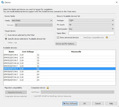
Because the PLCC and TQFP have different pinouts I first needed to find the correct MAX product to write for.  I am using the ATF1504ASL-25AU44-T which translates to this part from the conversion guide.

So I'll copy the existing project and set the part to EPM7064STC44-5.

 
I will also need to change the pins to match the new layout


Now I upload it as a 1504ASL ** NOTE the "L"

I had to make special jig to program the CPLD as used 1mm pitch not 1.25mm.

Here is the comparison between the 74HC00 and the CPLD.


 Here it is working just fine in my Z80MBC.


Friday, June 4, 2021

Building the : Cart64out by Sven Petersen ( kits available )

I've been looking at cart breakouts for quite a while now, but I've not had the skills or equipment to warrant one, that is, until now.  I recently bought and started using a Digital logic probe from Kingst and it it is a wonderful piece of kit.

So with my Kinst probe in conjunction with Sven's cart I am now looking at two more projects:

    1) Cart repair : I have two carts that I need to repair, both of which seem to be fine, but just don't work.

    2) Cart design : I'd like to try my hand at building a cart with a CPLD or FPGA.

Anyhow this build was pretty simple but I think It's going to be really handy.  The parts themselves are readily available apart from the cart edge connector, luckily the vendor was pretty good and I got a personalized deal for 30 units.  This is fine as I'll use them for board repairs and I may sell a few.

This is a bit of a niche project, I have quite a few spare boards and parts.

If you're in Australia and would like one please get in contact with me.  If you're outside of Australia, it's probably not worth while due to postage costs. 

The cost is $30 (AUD) for a full unassembled kit which includes:

  • 1 x PCB
  • 1 x edge connector
  • 1 x 40 pin connector
  • 1 x 18 pin header ( you can remove the 5v and GND pins if you wish like I have )
  • 1 x momentary switch
  • 1 x resistor network
  • 2 x standoffs
  • 2 x screws
  • 7 x jumpers
  • Standard Tracked parcel post to anywhere in Australia

I'm probably losing money on this I'm too scared to do the sums and find out, but it would be cool to see them other peoples hands.