Friday, January 6, 2023

Upgrade and Refit : A590 Hard Disk with Zulu SCSI

A few months ago picked up an Amiga A590 hard drive.  It still had the old XT hard disk in it but honestly I didn't expect it to work and it didn't.  It also had 1MB of RAM.

I'd been looking at SCSI replacement devices on the internet and how to put them into an A590 and what was compatible.  I saw a lot of people saying yes they worked and shots of work bench but nothing on how to actually do it.  I think in part because there can be a lot of assumed knowledge, where for old hands this is fine, but for newcomers it's a little frustrating.

So here is me doing it and documenting it, I hope you find it useful.

Today I Learnt : A590

 The A590 is an interesting beast . . .

Internal Hard Drive : it supports XT hard drives (old extinct hard disks) which you can basically ignore AND also a 50 pin connector for SCSI. 

External Hard Drive : it has a 25 pin connector for an external SCSI device.

Auto Boot : If you have the correct version of Kick start your Amiga can auto boot from the hard drive.

Looking directly at the back of the unit you will need to flick the first dip switch to enable this. If you have an old version of Kickstart you will need to turn the switch off and boot from the floppy disk image.  You will need to get the disk images if you don't have them.

Read more about this here get disk images from here.

Additional RAM : the A590 can add up to 2MB of additional ram to your Amiga 500.

Adding RAM

Adding ram was fairly easy affair, you will need to find some KM44C256AP-10 chips to fill the empty sockets.  The two columns  on the left hand side were empty on my unit.  Once they are in you will need to change the memory jumper, which is just to the side of the top row of memory chips and very clearly marked with 4 different options, Amnesia being the first and 2MB being the last.


You can use the Memory utility to check the status of your RAM ( from the disk images link above ).

Setting up ZuluSCSI

The ZuluSCSI was pretty easy to setup.

1) I changed the LED jumper a the front of the drive from XT to SCSI

I reamed out the holes in the bracket so the screws would easily fit.

I connected the 50 pin cable to the 50 pin connector.  

You DO NOT need to connect any power to the unit as it uses the power from the 50 pin cable.

Building the Image for the SD card was done on my PC using WinUAE.  I followed this easy tutorial.


And here it is in all of it's glory!

You need to use the A590 powerbrick or else your A500 will not turn on.  

Turn on the A590 power first ( it will do nothing ) then the A500.

You will most likely need to reset your A500 as it takes some time for the A590 to power up properly.


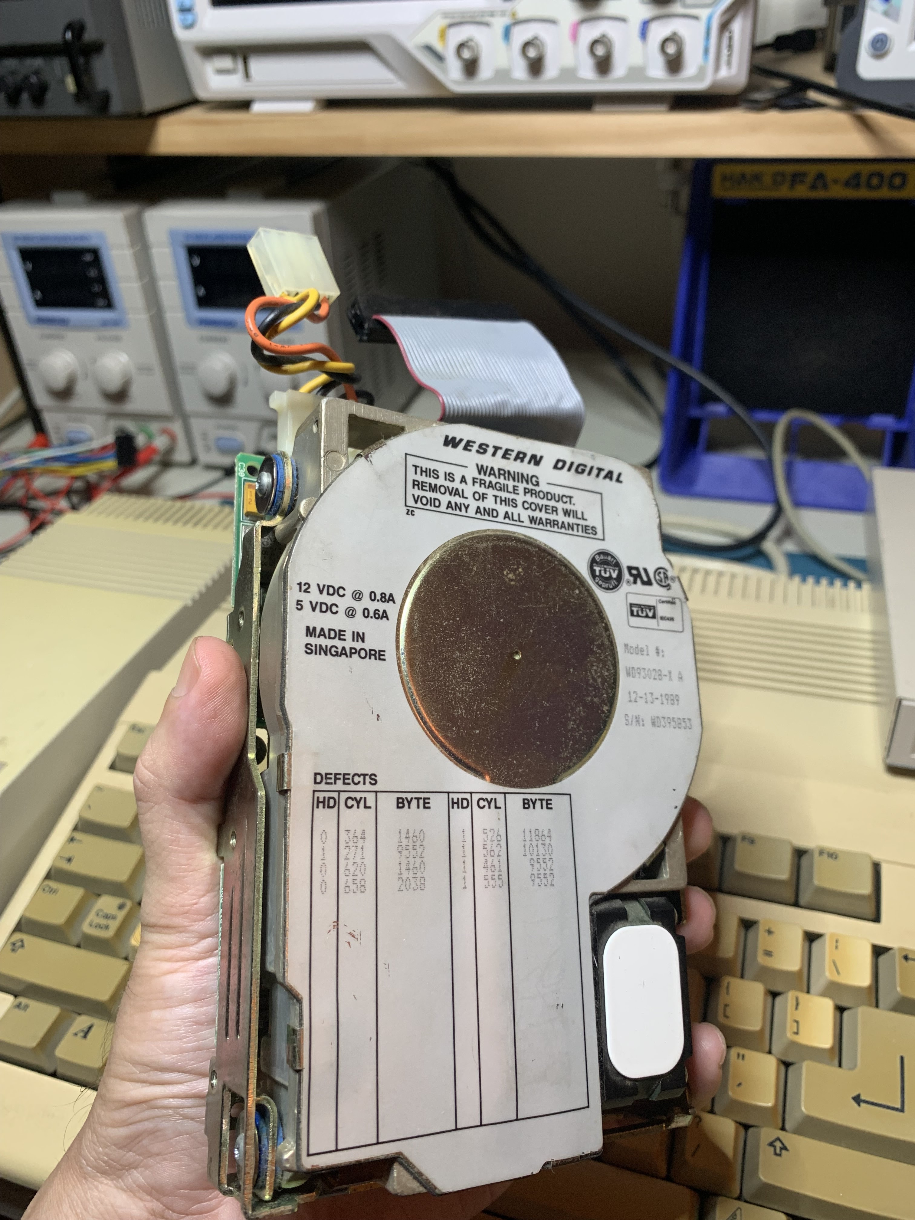
This the XT harddrive that doesn't work.


Repair : Sony PVM 9044QM - Black and white screen

Caveat : CRT Monitors contain lethal voltages, even when disconnected from power, do not attempt to open or repair any CRT.

Quite a few years ago now I bought a 9" Sony PVM which I use on my repair bench.  Just in the last half a year it has been playing up and after a few minutes of being on, loses all colour.

On the Internet I found two resources that were very useful to me.

The excellent video from RGB Bob and also this video from Retro Tech.

Initially I replaced the orange variable capacitors on the board as per RGB Bobs video, the parts are CV101 and CV102.


You can see the markings better once they are out.  Be sure to take note of the FLAT side, this will correspond to the components shape when you put it in.


The replacement also includes some bypass capacitors as well.  Solder in the new variable capacitors first and then put the bypass capacitors on the the back.  Please see RGB Bobs video for details and the replacement parts list.


Once they were in I was lost.  When I turned the monitor on it was still back and white.  I used a small flat head screw driver to adjust the capacitors but couldn't get the colour to return. I made sure I set each capacitor back to the original starting positions each time.
 
So I had a look at the main IC on the board and the soldering was a little average on the pins. So I decided to re-flow and refresh the solder there.


After that was complete it was still back and white.  So I went back to the Capacitors and tried again, this time turning them very slowly around an then back to the original starting positions.
 
No luck on CV101, so I put it back to it's original position.On CV102 I got a small blip on the screen, not colour but a flickering of the image. I VERY VERY slowly turned the capacitor back over where the blip occurred and the screen suddenly displayed full colour in all of it's glory!
 
So the lesson here is, if you have to tune it back in, be very very patient and watch the screen like a hawk for minuscule changes. 


Monday, January 2, 2023

Repair : HP D2827A / Daewoo CMC518X


Caveat : CRT Monitors contain lethal voltages, even when disconnected from power, do not attempt to open or repair any CRT.

So more than a few years ago I ”rescued” a couple of HP D2827A monitors. One was prefect, the other one would turn on and the front panel and lights worked but the CRT had no display at all and did not exhibit the high voltage thump and crackle as it powers up. Try as I might, I could not find a repair manual for the Monitor.
 
 
I've been putting the repair of all of my monitors for years.  Finally after years of repairing my computers and their power supplies and reading untold many blogs, repair guides and videos I felt I was ready.  Also I bought a proper discharge tool.  The thought of using a home made tool was totally unpalatable.


Opening it up and looking at the motherboard marking it turned out the monitor was a re-badged Daewoo CMC518X monitor and the service manual was readily available.
 
It was fairly easy to find the culprit Q104, a transistor KTA1273-Y.  This was mainly due to the huge burn mark and the exploded solder from the center pin. Unfortunately that part is no longer available, luckily a drop in replacement is still available KSA928A-Y.


 I took the original part out and cleaned it up a well as I could before putting in the replacement.  There was tiny balls of solder all over the bottom of the board which I painstakingly removed.


There are a couple of things that are a little out still. There is slight bow in the picture that’s not adjustable.  The brightness and contrast are set up to max. However the monitor is now usable (shown connected to my MiSTer).  Further troubleshooting will need to wait until after I've completed the other unfinished pre-COVID-19 projects littering my workroom.


Repair : Amiga A520 : Video Modulator

I had bought a couple of non-working A520 modulators for a new project, however with the advent of COVID-19 and general lack of time due to life I decided I'd just fix them and make use of them.

Of the two modulators I had no picture at all and the other looked like this.  However both have the same problem, the MC1377P - Colour Television RGB to Pal/NTSC Encoder.

Opening the case

 The A520 is a friction fit case, there are no screws to remove or catches to unclasp.  The easiest way to pull the two halves apart is to use a plastic spudger to slowly lever the two halves evenly apart.  It is important not to twist the case or lift it unevenly!


You can see here the four legs that hold the two halves together.  The small rods insert into the larger hollow rods and hold very tightly.

The next thing to do is the remove the only two screws in the unit that hold the PCB to the bottom half.


Replacing the MC1377P

Replacing the chip is a fairly easy affair as the PCB is single sided.  Using a desoldering tool is a breeze and the part just falls out.


As with all DIP replacements it is good practice where you have vertical clearance to solder in a socket.


Lastly lets give it a test.  That is so much better.